Or... HOW TO BURN A HOLE IN THE IONOSPHERE ON SIX METERS
Way back in the last century, circa 1987, I was fortunate enough to be the Chief Engineer of a brand new television station that I built from the ground up, K5 in Honolulu. We worked closely with Larcan, Inc.
of Canada who were developing an all-solid-state high power television transmitter in the 20 kW range. Prior to this, high power TV transmitters had always relied on at least one vacuum tube for the high power RF amplifier. Larcan developed a 1 kW module with four dual-FET devices on a massive heatsink. The FETs were interconnected with RF striplines and combiners, so the modular amp was completely broadband, with absolutely no frequency-dependent tuned circuits. Larcan combined several racks of stacks of these 1 kW modules with more stripline combiners and the result was the world's first, all solid state 22 kW TV transmitter that I installed! This was a TV transmitter engineer's dream! It was a flat, broadband TV transmitter with no tuning adjustments needed... ever. The Larcan M-series TV transmitters soon became the world's most successful TV transmitters, and the technology developed then is still in use in today's digital TV transmitters that are even more demanding.
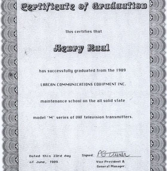
I was one of five TV engineers that graduated from the first LARCAN maintenance school at the factory outside of Toronto, June 23, 1989.
Over the years, I fantasized about how great it would be to salvage one of the solid-state PA modules and turn it into an amateur radio amplifier. With the shutdown of analog TV in 2009, the opportunity presented itself as I salvaged a couple of the 4-device 1 kW modules from the old K5 transmitter before it was scrapped after 22 years of excellent service. But I also was able to salvage some 1.5 kW modules from the low-band (Ch.4) transmitter where I work now. These modules have six devices on them, and they ran a little warmer than the original 1 kW modules, but I figure they would be a little more rugged for more power, too. These modules worked in the 66-72 MHz low band Channel 4 frequency. (For those who don't know, the entire 'Low Band' of former analog TV channels was shut down during the digital TV conversion, and that spectrum returned to the FCC for other uses.) There were only very minor tweaks to these modules to optimize their 'flatness' on channels 2-3-4 or on 5-6. For all practical (ham) purposes, these broadband modules will work fine at 6 meters, 50-54 MHz.
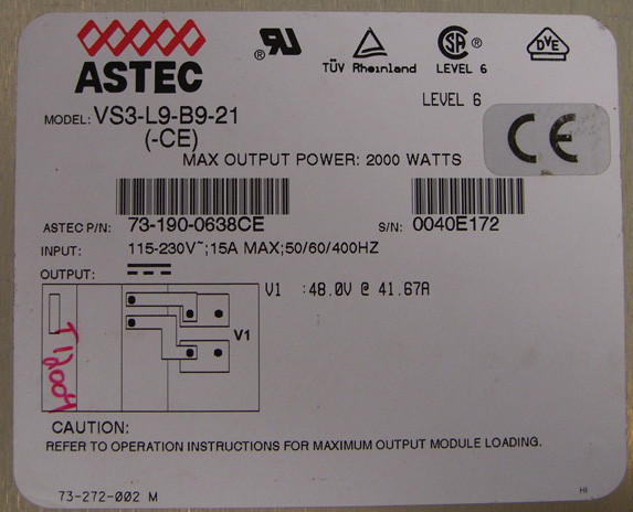
I've kept an eye out over the years for other parts that would potentially be useful for this longer-term project. The modules work on a 50 volt supply line, and the original transmitter had a massive, 3-phase transformer, rectifier bricks, and a floor full of electrolytic filter caps for the power supply. Copper buss bars ran up the racks to supply 50 volts at several hundred amps to power the transmitter. I got lucky in my travels and was able to salvage & repair a couple of ASTEC switching supplies from other transmitters driver modules. These supplies are rated at 48 volts at 41.67 amps.... that's 2 kilowatts! Perfect for powering one of these 1.5 kW rated modules.
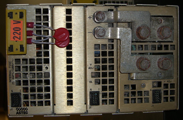
It's a little crusty after years of service, but it still works!
At ALL ELECTRONICS I found a 50-amp meter and 50-amp shunt for it that will be useful for monitoring the current draw of the PA module.
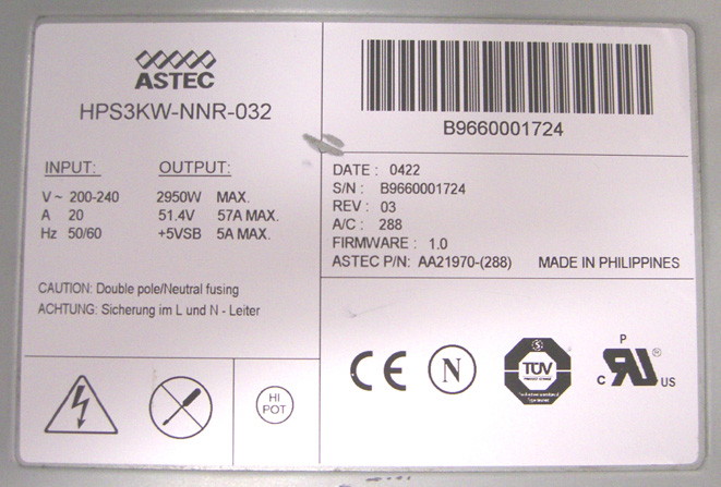
And then one day on eBay I found an ASTEC 3kw power supply that will be capable of taking the 1.5kW module up to full power. It should be realized that these FET amplifiers consume a lot of DC current for a given RF output. Efficiencies range from around 35% to 45% for these amplifiers. That's why it takes such a big power supply.
FILTERS
Being that the PA modules are broadband, they will also amplify any garbage that is put into them. While most tuned amps are capable of generating their own harmonic spurs and need filters on the high power output, this amplifier is different. Here we can apply bandpass filtering at the low-power input stage so the signal meets FCC spec. and we can expect the signal coming out of the amplifier to maintain that harmonic spec without the amp adding any distortion.This makes the filtering components smaller and easier to deal with.
A few years back I ran across a 6-meter low pass filter design for 1 kW with a good second harmonic notch, and I built one. The design is by Dick Stroud, W9SR, and is found in the 2007 ARRL Handbook. This can be added to the input of the PA for extra protection on 6 meters and we don't really need the high power capability on the filter. The second harmonic of a 6-meter transmitter falls in the upper portion of the FM broadcast band, so it behooves an operator to have a good filter, with a good
2nd harmonic notch. People will surely notice if you don't.
If you have some in-band junk to deal with, there is also the old standby stripline Notch filter as shown here from the 1980 ARRL Handbook. I used to live near a Channel 2 TV transmitter and had some pretty horrible video sync buzz in the upper portion of six meters, around 53-54 mHz. and I built and used that stripline filter to quiet my receiver down a bit. Since 2009 the old analog low-band TV system has been shut down now, so it is no longer a problem.
The good news is that you can get away with a small, low power filter on the input of this amplifier. The amp module is spec. at +20dB gain, so for only 10 watts input you can expect 1000 watts out.
I checked with my friends at Larcan, and they gave me permission to publish images and schematics of their old, now obsolete low-band modules. So here is what it looks like.
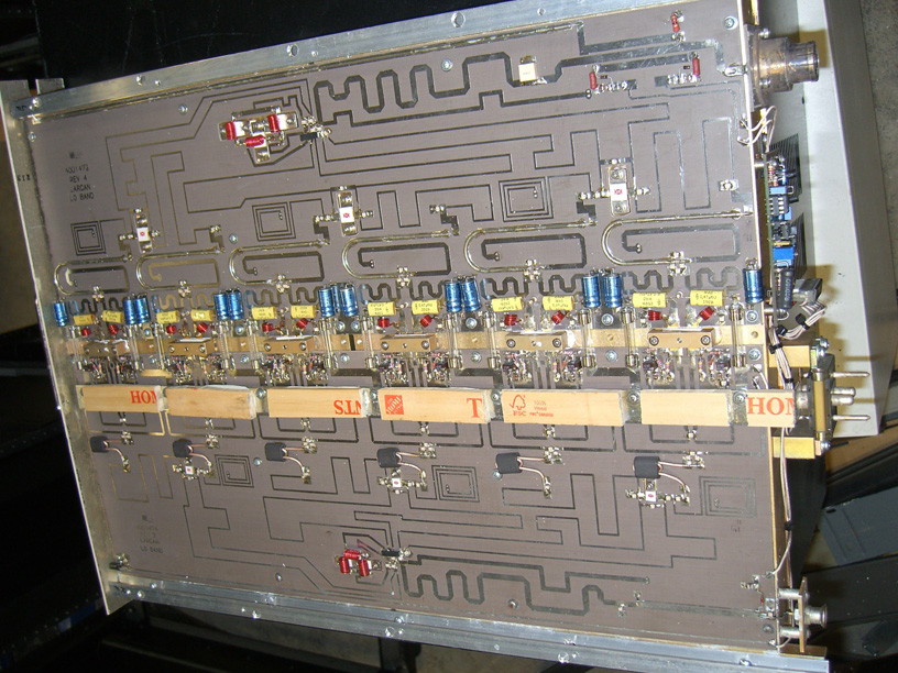
The modules were designed to run standing vertical like this in slide-in racks. The entire backside of the module is a massive extruded heatsink, finned vertically for airflow from bottom to top. When stacked with dozens of other modules in racks above or below, a lot of airflow was needed to remove residual heat. For amateur PA use of a single module, I don't think heat buildup will be as much of an issue as it was running 24/7 in a large transmitter array, and I plan to run it horizontally with the heatsink across the bottom. I noticed during sweep tests with the module basically "idling" that it did get somewhat warm, so I am looking for some small squirrel-cage type blowers that I can duct in along one edge of the heatsink for cooling. Let's see... 12 sections biased at 500ma each is an idling current of 6 amps. At 50 volts, that equals 300 watts of idling heat. Yup... I think it needs fans.
The only thing odd looking above is the wooden sections of yardsticks across the middle. They are glued to the power buss bar to provide insulation and bumpers for the covering panel we will add later. The module input is at the lower right corner. It is a special slide-in coax connector that I later removed and replaced with a regular BNC connector. All across the bottom circuit board you can see the signal is split into six small baluns where it becomes parallel push-pull into each device. The actual FETs are mounted under the gold colored anodized blocks across the middle of the module. Each 'device' is actually two FETs in a single package. A Motorola MRF-151G is a replacement for these devices. On the upper circuit board the sections are combined once again and routed to the output connector at the top right. Each device is surrounded by it's own support circuitry, part of which supplies a DC bias to the device. There are 3AG style fuses on each side of each device, rated at 7 amps each. If a device fails, it usually shorts and causes a fuse to blow. Standard maintenance on this transmitter was to check for blown fuses, and to replace the FET device where blown fuses were found. Also, the new device must be given the proper DC bias current of 500 ma quiescent, with no drive. This was done by opening all the fuses on the module except one side of the device that had been replaced. Power on 50 volts with a current meter inline, and adjust the tiny trimpot next to the device to set the static current at 500 ma. Then open that fuse and engage the other side of the dual device, and again set that side for 500 ma. with it's trimpot. And that's all there is to replacing a device on the module.
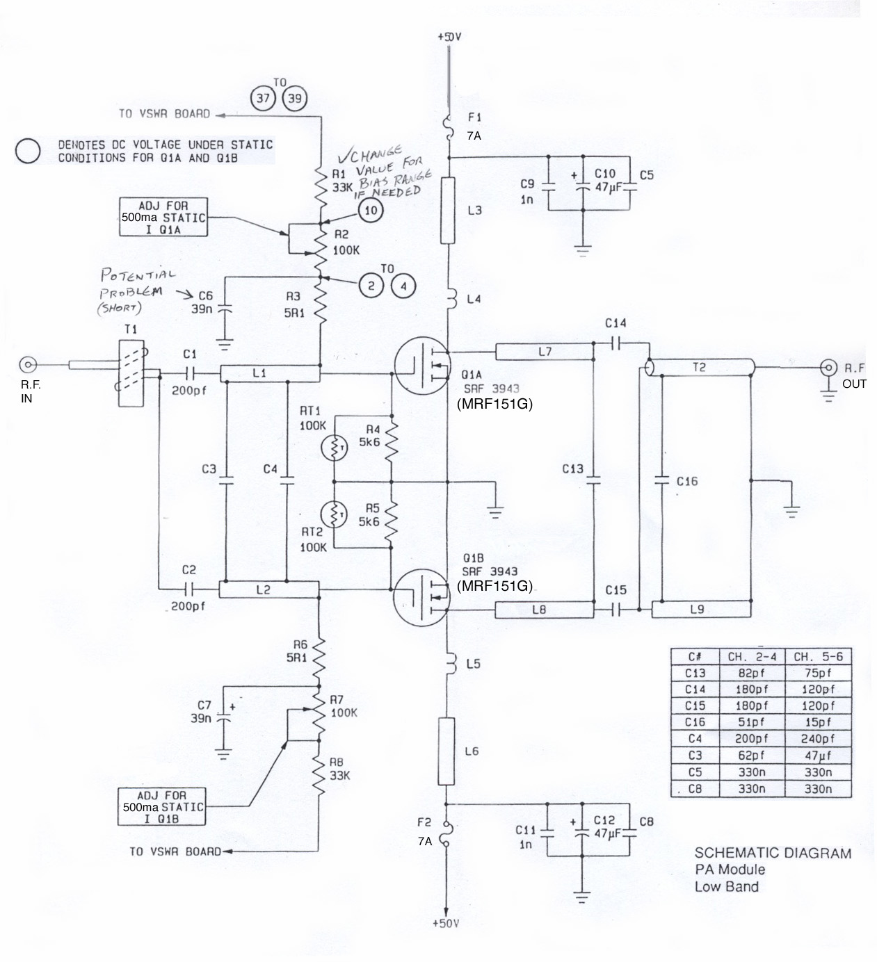
This is the schematic diagram of one active device section of the amplifier. Not shown are all the passive stripline splitters and combiners that interconnect six of these sections on the module. Note the capacitor chart. You can see that only minor trim value changes were made for the upper two TV channels of the low band. These were to optimize the 'flatness' of the broadband module for analog TV service, which is an amplitude modulated (and pulse) signal from 0 to 6 MHz wide. TV is much more demanding than the SSB or CW service we are asking of it in amateur radio service.
MANUAL
A complete 20-page manual in PDF form describing the whole module and test procedures may be downloaded here:
http://www.gemoto.com/documents/Larcan_20Page_PA manual_1kW_LB.pdf
The manual is for the 1kW module with four devices and associated stripline splitters and combiners. The module I have here is a 1.5kW version with six devices, but the concept is the same.
By the way, the New England GEMOTO.com group has lots of useful information and pictures of converting these modules also.
PACKAGING
Now if I run the module in a flat horizontal position, I need to cover all this RF circuitry and support some more subassemblies on top. This is fairly simple to do. I drilled and tapped the slider rails on the long edges of the module and mounted 1/2" aluminum "C" channel along the sides like this:
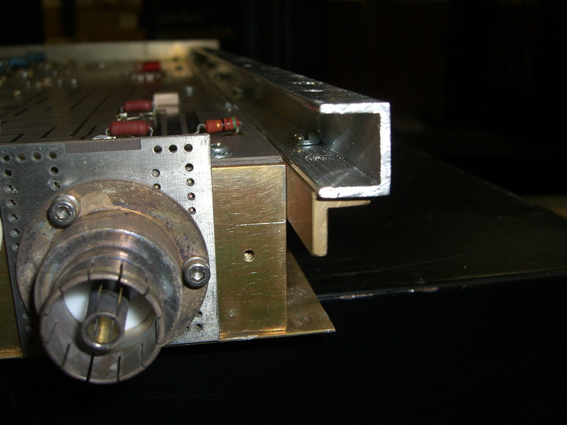
This provided enough height to clear all the components on the PC boards. I cut a thick aluminum rack panel to size for the module and screwed this to the top of the C-channel to cover everything.
Now the highest point on the electronics turns out to be the power buss bar. This is where I glued the wooden yard sticks to provide insulation and support as the metal cover panel may bow downward under the weight of stuff on top of it.

As you can see, I still have a bit of clearance between the wooden stick and the top panel. I will glue another shim piece of top of these to fill the gap to the metal panel, and provide some firm support for the panel so it does not bow under the weight of additional assemblies on top. With only 50 volts on the power buss, I figure that dry wood is adequate insulation. The panel is frame grounded along the mounting rails, and provides RF shielding over the active components and striplines.
My friends at the Larcan factory have an RF adapter for the output connector to take it down to a standard type-N connector.
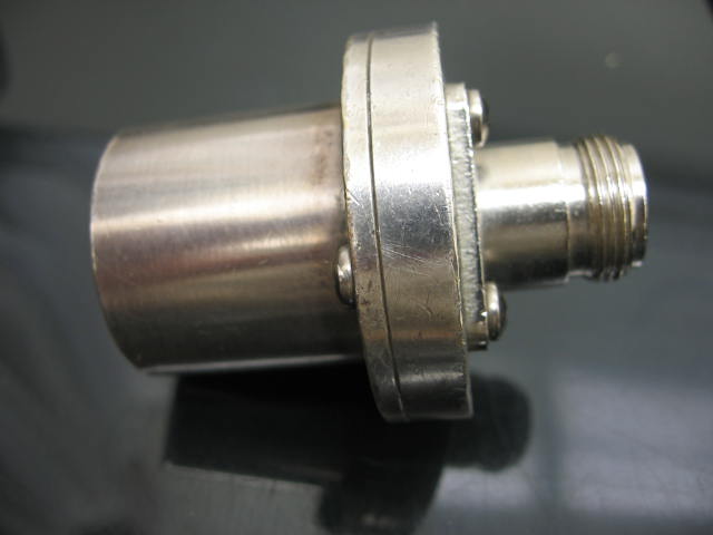
This custom adapter is Larcan Part number 20B1261G2 and is available from the Larcan parts department contact, Debbie Degenaar: email ddegenaar@larcan.com
The price of the adapter is $150.
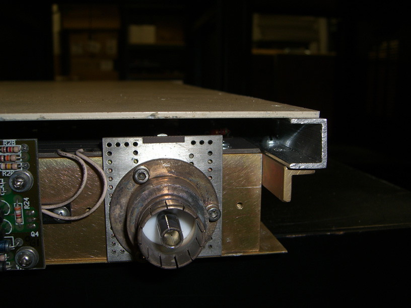
Of course I'm a cheapskate DIY guy, so I salvaged a large connector from the backplane of the transmitter. For about $6 for a type N connector and a couple more bucks for some brass 4-40 screws and nuts, with careful application of a LARGE soldering gun to this big heatsink, I came up with this...
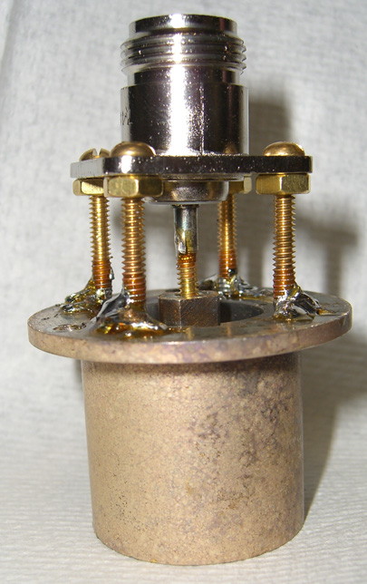
I think I will be soldering some brass or copper sheet around the four outer posts to protect the inner conductor. I really don't want this to become a bug (or finger!) zapper when RF is applied
VSWR Board

Along the back, or connector edge of the module is this little board. Larcan calls it the VSWR board. As transmitter engineers, we called it the "Green Light Board". It serves a number of essential functions in running the module. This board regulates the +50 volt supply down to a 39 volt line that supplies bias voltage to all the devices. It uses this bias line to control the module gain and throttle it back in the event of a VSWR fault. There are stripline directional couplers on the input and output of the module, and this board monitors the total gain of the module with one comparator circuit. This comparator drives a green LED on the front panel to indicate the module is OK. In the event one device fails, the comparator level drops and shuts off the green LED to indicate a module fault. The sensitivity of this circuit is set by the only multiturn pot on this board. This little board also performs important step-start functions for when the module is hot-plugged into a working transmitter array. These functions are detailed in the 20-page manual listed above.
SWEEP TESTS
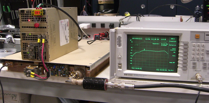
The module idles at 48 volts and 5.93 Amps. This tells me that twelve bias sections are set very close to 500ma each.
I had initially hoped that this module would be useful down into the HF bands. The FETs are inherently capable of it, but I guess there are limits to the bandwidth of the striplines and splitter/combiner circuits. As you can see in the sweep test below, gain falls off as we go down in frequency.
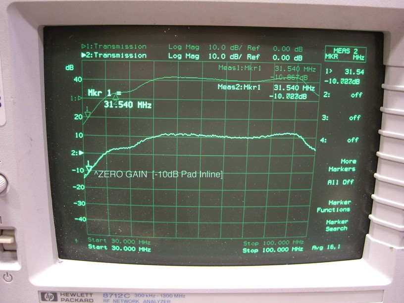
At 31.5 MHz the module gain is essentially zero. It won't even work for 10 meters.
On the upper end the module is good up to 95 MHz before rolloff gets serious.
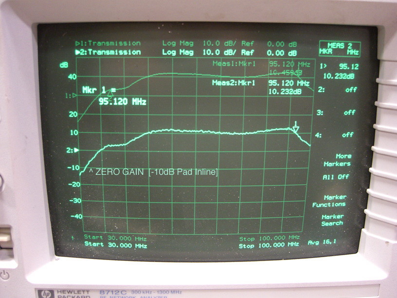
So that's what the bandpass of the module looks like.
The following two markers show the gain at the low and high ends of the six meter band.
Add 10dB to the screen figures shown, as we have a -10dB pad inline with the amp output.
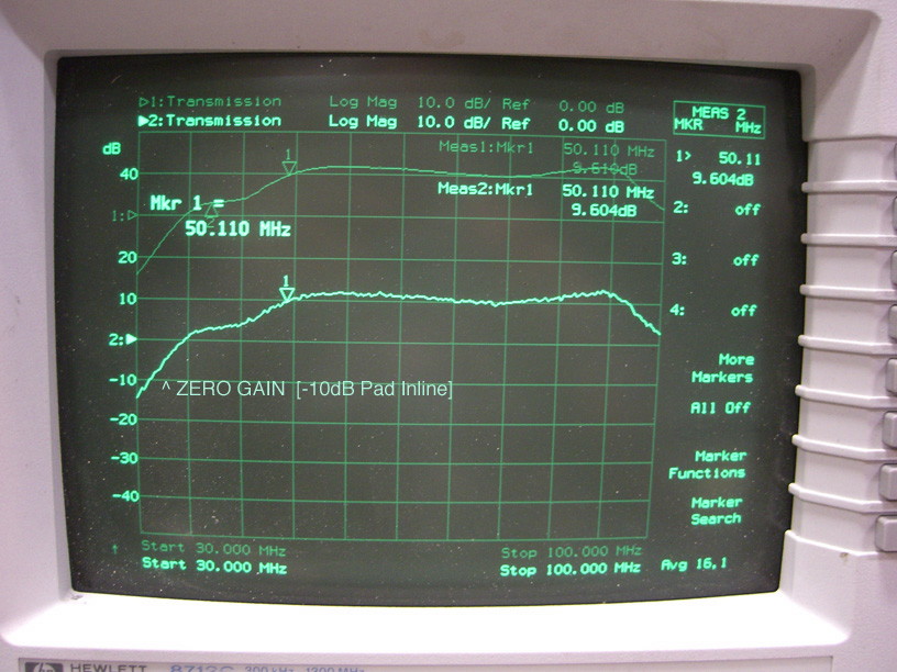
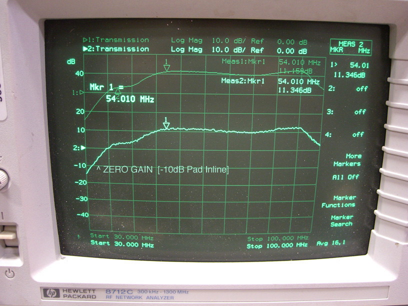
So we have 19.5dB to 21dB gain across the six meter band, 50-54 MHz.
Five watts input will get you a hot 500 watts output!
STAY TUNED...
NOTE: These tests in no way suggest out-of-band capabilities on behalf of Larcan and this use is not supported by Larcan. These are deliberate, non-normal tests when used outside of factory approved limits for amateur radio uses.
I will have a limited number of these modules available for licensed amateur radio operators to experiment with. Contact me at
kh6hak (at) arrl (dot) net
for more information. I will no longer list these things on eBay due to their ignorant, customer antagonistic, false allegations about "illegal CB amplifiers" ! Sheesh!
The modules are heavy at over 35 lbs., and packing and shipping from Hawaii are considerable expenses.