After some unsuccessful tries to uplink to AO-7 satellite and make a mainland contact, I decided I needed more UHF gain on my uplink antenna. Commercial antennas are very expensive, and I'm a DIY guy, so I looked around for some construction plans. The best, simplest, cheapest plans I found were by Kent Britain, WA5VJB, and found here.
I constructed my version out of 1/8" bronze brazing rod elements and 3/4" PVC pipe. It's easy to shape the elements, drill the pipe, and glue the elements in place with 'goop' or some other cement. I used a PVC T-fitting at the driven elements for an access hole to connect the coax. I used Belden 9913, low-loss RG-8 style coax, and I found I could squeeze two feedlines down the pipe for the two polarization feeds. The horizontal and vertical antennas are physically offset by 6-1/2" along the boom to provide the circular polarization desired. Here is an image of one feedpoint and the coax connection inside.
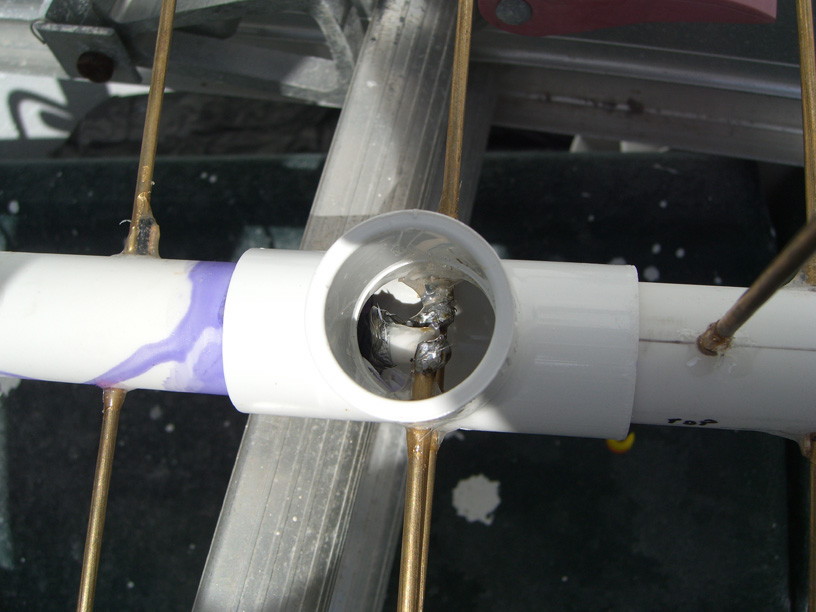
I capped the front end of the boom as it will be aimed upwards at times, but I decided to leave the feedpoints and rear boom open where the coax exits. This will provide some drainage. To waterproof the coax joint seen above, I found a "Flowable Silicone" clear windshield and glass sealer at an auto parts store. The stuff does not skin over in globs like regular silicone does. It first 'melts' and flows into the smallest crevice and then hardens slowly. It does not contain acetic acid to corrode electrical joints, either. The result is that it permeates the open coax braid and joint, soaks in, and skins over to waterproof the whole area with a silicone RTV skin.
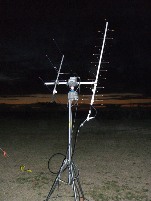
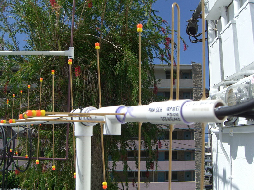
So here's what the antenna looks like. After nearly poking my eye out while adding rods, I got some bright plastic beads and glued them over the element tips for safety. This is the 11-element CP version for 435 MHz satellite use, with a theoretical gain of 13.8 dBi.
Essentially we have two separate Yagis with two feedlines coming out the back end of the boom. Phasing is determined by physical offset spacing, so the two antennas need to be fed In-Phase. To accomplish this I purchased a commercial 70cm power divider from M2. This is essentially a 1/4 wave piece of 35 ohm coax that will transform a 25-ohm impedance to 50-ohms. So we connect two 50-ohm antenna feeds in parallel at one end (25-ohms) and transform it back to a single 50-ohm feedline.
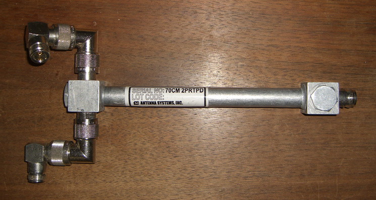
The "goofy foot" ends are type N elbows that were required to mate to the offset feedlines at the back of the antenna. These must be kept 'In-Phase', so both legs must be the same length, same connectors, etc. The net result is an in-phase power divider that splits equally when transmitting, and combines the H & V received polarizations upon receive. The power divider was around $90. Not cheap, but hard to duplicate perfectly. Overall, it was still a cheap yagi, compared to a commercial antenna. Of course this expensive part is not needed if you are building a single polarization Yagi... dirt cheap!