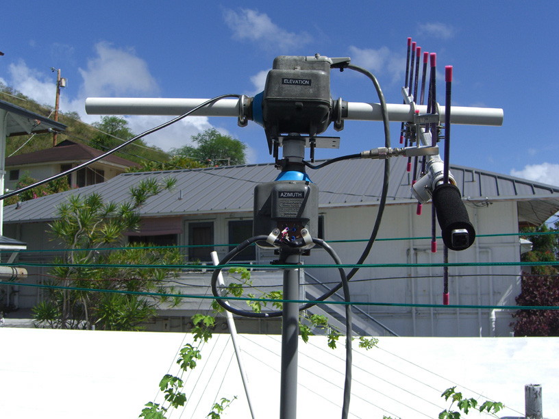
A flat metal plate is drilled out for the four mounting bolts of the sideways EL rotor, and a conduit knockout punch for a 3/4" fitting is adapted to 1" PVC pipe, which slides thru the mast mount of the AZ rotor below.
Be aware that the sideways mounted EL rotor is NOT WATERPROOF in this position, and it WILL fill with water!! If you leave this outside for any length of time, I would fashion a small 'poncho' of plastic sheet to provide a rain cover for the rotor(s). I left this setup out for just a couple weeks, with a couple rains, and it seemed to leak in thru the wire terminal area and filled the bottom of the casing. I poured it all out and dried it out, but the damage was done. The motor began to smoke as I tested it and promptly died. I got another rotor, and the lesson was learned. I drilled a small weep hole at the low point, but the structure inside can still dam up small puddles of water. Rain seems to ingress also thru the sideways rotating joints and there is no way to waterproof those. Also be sure to put some good heavy grease on these joints when you have the rotor apart. They are not really designed for side-loading like this, but if you keep them well greased and loaded within reason they seem to work fine. Make a plastic 'poncho' cover for it all. Greg, KO6TH, tells me his has been working for years this way with no problems.
==================================================================================
After much prodding from various amateurs I got into amateur radio satellite operations and learned how to work the FM birds with as little as a handheld antenna and handheld transceiver. Complexity progressed to using a computer to track the satellites and tune a larger Icom IC-910H satellite transceiver for doppler shift. The software also had the capability to steer an Az-El rotor to track the satellites across the sky. Now most of my satellite operations are knockdown portable style for field day operations, and I cannot afford an expensive commercial rotor system with a big tower.
Back in the 1960-70s the small Alliance U-100 rotor was ubiquitous for TV antennas. The rotor was small and lightweight, and had the 'feature' of the rotating mast sliding completely through the rotator tube mount. This feature makes it easy to mount one rotor on it's side and use it as an elevation rotor. I picked up a couple of these U-100 rotors cheap on eBay. They are also still available from Norm's Rotor Service at :
http://www.normsrotorservice.com/press3-alliance.htm
I mounted two rotors together with a hardware plate to function as an Az-El pair as shown on Norm's Rotor website. But building a controller that would interface to my MacDoppler computer software was problematic. VE5FP wrote a good article for the Dec. 1998 QST about controlling these rotors, but unfortunately that particular microprocessor controller is no longer made. Some further research showed that Greg Dolkas, KO6TH, had constructed a rotor interface with a Parallax BASIC STAMP-2 microcontroller that was programmable in BASIC.
http://home.wavecable.com/~ko6th/
This controller looked good, but I abhor using relays with a microcontroller circuit to drive external motors. Indeed, Greg had some problems that required some 'spark suppression' techniques on the relay contacts so as not to upset the solid-state microcontroller. My solution was to 'borrow' the elegant, solid-state motor control circuits that VE5FP used. This consists of a Crydom 4-section solid-state AC relay to drive the rotor motors. The 24 Volt reversible AC motors have three connections arranged like this:
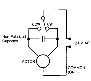
Direct AC power is fed to one leg of the motor, and the other leg is fed out-of-phase power thru the Non-Polar capacitor. This determines which direction the motor rotates. When the switch feeds the other leg directly, the motor reverses direction.
The Crydom CTX240D3Q solid-state relay switch has a nominal input impedance of 270 ohms, or about 15ma sink at +5 volts. We could drive this directly from the logic, but this is close to pushing the 20 ma total output limits of the STAMP-2 microcontroller, so it is a good idea to use the IRF510 MOSFET drivers to switch the load from a high impedance input. The current handling of the IRF510 is overkill in this application, but they are cheap and commonly available. At $87 the Crydom relay is the most expensive part, next to $50 for the STAMP-2. This gives us Triac zero-crossing AC switching with no noise to upset the digital circuits. And no mechanical relays!
The other problematic item is the pulse contacts on the rotors. Bringing contact closures down a long tower cable and directly into a digital circuit can lead to all kinds of static and induced EMF problems. I elected to run the contact closures into an Opto-Isolator circuit. The contacts drive an LED in the OPI 110 Opto-Isolator, which is coupled to a phototransistor that provides an open collector switch to ground on the isolated digital side of the circuit.
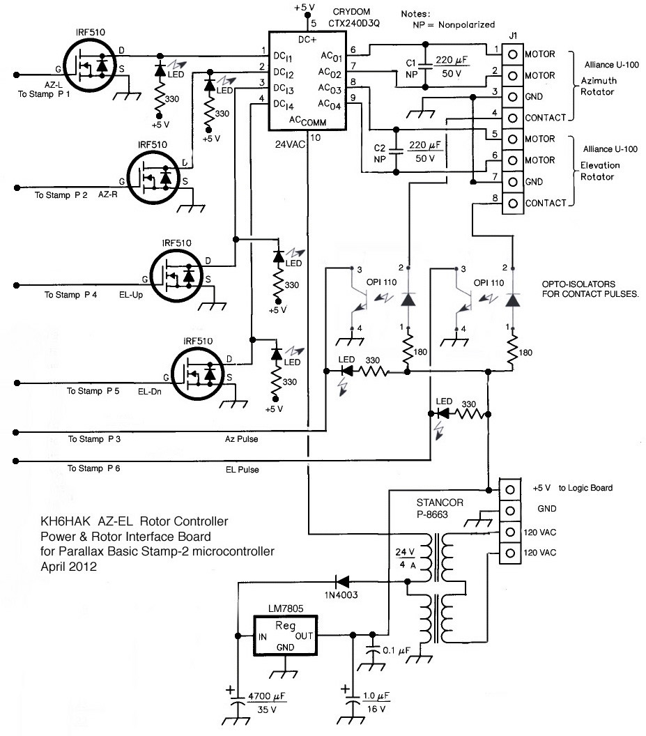
I realize the schematic above is a bit hard to read on the webpage here, where it is shrunken. Just rip the image onto your computer and open the JPEG to full size for full resolution.
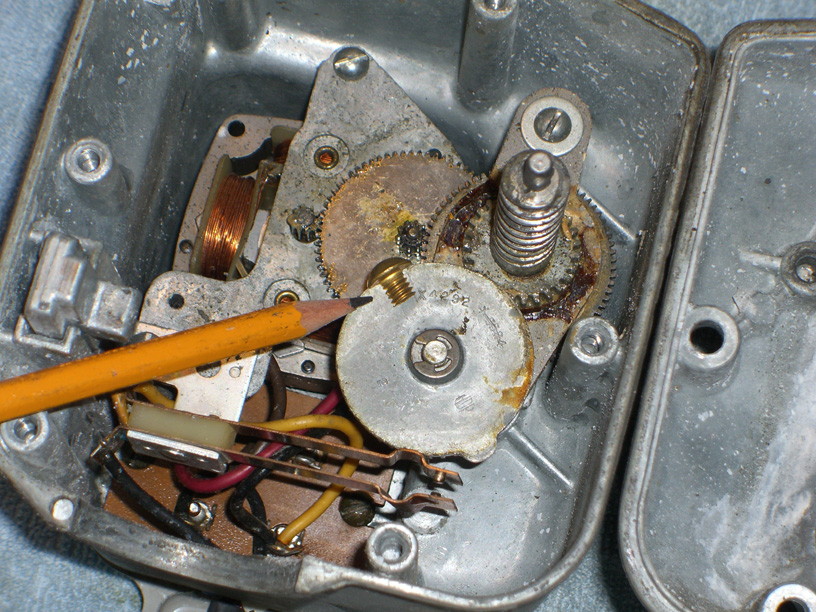
The other minor problem that Greg noted was the inherent 10-degree resolution of the rotor. The rotor has an internal cam that rotates every 10 degrees, with a bump on the cam that trips a leaf contact switch.
I decided to increase the resolution to 5 degrees by adding a second bump on this rotating cam. This was done by splitting a brass 1/4x20 round-head screw lengthwise with a dremel cut-off wheel and epoxy gluing the flat side of the screw to the cam, opposite the original bump. Be careful with the position of the screw head and be sure it clears the other gears as the cam rotates. The Basic software from the KO6TH design was modified to calculate position from pulses provided every 5 degrees now.
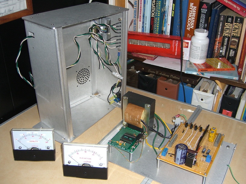
A lot of the parts were sourced cheaply on eBay. The enclosure box was from a metal fabricating shop that was selling them cheap because they had 'manufacturing marks' on the brushed aluminum, and not suitable for first-class customers. I figured it would only be a short time before I was adding my own 'user marks' on the enclosure, so it wasn't a problem for me. The 0-1ma large face meters were from a military surplus dealer where I also found the Stancor 8663 transformer. The power transformer is 24V at 4 A with a center tap. This is enough current to run both rotor motors simultaneously if you command it. The center tap was used for a 12 volt supply to feed a 5 volt regulator for the logic supply. Put a big heatsink on the 7805 regulator. It generates a lot of heat dropping 12 volts down to 5 volts.
Here you can see the power and motor control board on the right, the green STAMP-2 carrier board in front of the power transformer, the meters with modified scales, and the chassis under construction.
There are LEDs added at critical parts of the circuit to provide troubleshooting and also indicate proper operation of the circuit. These are on the circuit board and also brought out to the front panel. I'm a great fan of indicator lights. It's gotta light up if it's working.
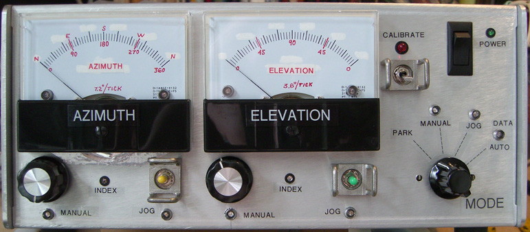
Front panel construction complete, and all the lights work. At this point the switches are hardwired to the motor control board and the box will drive the rotors in manual mode.
Next module is to complete the STAMP-2 board and interface it, and program it.
Computer Control
The whole point of all this was to get a computer to control the Az-EL rotors and aim the antennas automatically. Again I would like to acknowledge and thank Greg Dolkas, KO6TH, for the inspiration, documentation, and source Basic for this project. The last time I did any Basic programming was circa 1984 on an APPLE ][ and coincidentally, that was for an Az-El motor controller for a satellite dish at a TV station. So I muddle through the software and tweak it a bit for my 5-degree rotors.
There are several different satellite tracking programs for Windows machines, and since I am a Mac user (Shameless plug: "Once you 'Mac', you never go back!) I use an excellent program called "MacDoppler". Almost all of the tracking programs will provide data to the popular commercial rotor systems, and one of the more popular and easy data interfaces is to the Yaesu serially controlled rotor. It uses a simple command language. The serial data contains a "W" followed by the azimuth and elevation values in degrees, separated by a space, and followed by a carriage return.
W090 030 would indicate a position due East at 30 degrees elevation.
The Stamp code receives the serial data stream using the SERIN command:
SERIN SERIAL,BAUD,2000,NOSERIAL,(WAIT("W"),DEC AZINPUT,DEC ELINPUT)
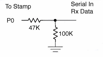
Please note that this data input does NOT go into the existing 'data port' on the stamp carrier board! That data port is used exclusively for programming the stamp and storing data in the stamp ROM. Once the Stamp is running the program we put into it, it is told to look for data coming in to pin P0.
The decimal values for azimuth and elevation are converted to the internal form, and compared to the current positions of the rotors. If they are different, a call to the MOVE routines (created for the manual modes) is initiated.
The controller interface has several different modes of operation, selected by the front panel MODE switch.
AUTO =Receives data from the serial input and steers the rotor automatically. The yellow LED in this switch position will indicate data activity from Stamp P13.
JOG = Indicated by Green LEDs on the mode switch and under toggle JOG switches. Used to manually jog the antennas for incremental positioning.
MANUAL =Indicated by Blue LEDs on the mode switch and under the pot knobs. These knobs are used to manually adjust the meter to a predetermined position. Shortly after adjustment stops, the 'MOVE' command internally takes over and moves the antenna to the predetermined position.
PARK =Turns off the movement routines and lets the antenna park in it's present position.
CALIBRATE This is a separate toggle switch with a red LED indicator, described below.
The Parallax BASIC STAMP-2
Information on the microcontroller can be obtained from the Parallax website here.
This project is constructed from the BASIC STAMP-2 microcontroller, and I used the Stamp-2 'carrier board' to construct the interface circuits and mount the microcontroller chip. There are sixteen user-programmable pins on the microcontroller that we interface here, labeled P0 thru P15. In addition, the Stamp-2 has pins for power, reset, and serial programming data. Our controller interface pins and their functions are listed below.
P0 Serial data input from the computer program driving the 'Auto' mode.
P1 Output "LEFT" or AZ-Decrease. Hi drive to mosfet gate input on motor control board.
P2 Output "RIGHT" or AZ-Increase. Hi drive to mosfet gate input on motor control board.
P3 Input AZ INDEX pulse. Lo (Gnd) switch from (Opto-Isolator) rotor contact switch.
P4 Output "UP" or EL-Increase. Hi drive to mosfet gate input on motor control board.
P5 Output "DOWN" or EL-Decrease. Hi drive to mosfet gate input on motor control board.
P6 Input EL INDEX pulse. Lo (Gnd) switch from (Opto-Isolator) rotor contact switch.
P7 Input MODE Switch, least significant bit (LSB)
P8 Input MODE Switch, most significant bit (MSB)
P9 Input AZ pot
P10 Input EL pot
P11 Output AZ Meter
P12 Output EL meter
P13 Output 'Serial Data' LED driver. Yellow LED on MODE switch 'Auto' position.
P14 Input JOG switches (both). Resistive divider selector.
P15 Input CALIBRATE switch. Lo (gnd) active.
We have seen the P0 serial interface above. Pins P1 thru P6 interface to the power and motor control board schematic way above. To move one of the rotors, the appropriate line is engaged (Hi). The contact pulse input is polled until the right number of counts is seen. Then the motor drive line is released (Lo).
HIGH RIGHT ;start motor
AZRIGHT:
GOSUB AZINDEXWAIT ;wait for contact closure
AZPOSN= AZPOSN+1 ;update the current position
TEMP=AZPOSN*AZCOUNT*32/34 ;update the meter
PWM AZMETER, TEMP,50
IF DEST>AZPOSN THEN AZRIGHT ;test if done yet. If not, wait for next contact closure
LOW RIGHT ;turn off motor
PAUSE MOTORSTOP ;wait for things to settle down before continuing
The subroutine to wait for and debounce the rotor's contact closure pulses is as follows. For contact bounce I use a simple delay (pause), which is timed so that the contact pulse has completely closed, finished bouncing, opened, and the rotor is in the middle of the gap to the next pulse. I chose to isolate the rotor's contacts from the digital circuitry by using the opto-isolators to provide a transistor switch to ground at the motor control board. LEDs on the motor control board and on the front panel centered below the meters flash with the the index pulses to show that the rotor is indeed moving properly.
AZINDEXWAIT:
IF AZINDEX=0 THEN AZINDEXWAIT ;if already at index, wait first (ie:contact is closed)
WAIT1:
IF AZINDEX=1 THEN WAIT1 ;wait for index to start; 0=closed,1=open
PAUSE AZINDEXT ;delay for switch bounce and for end of pulse
RETURN ;done
Lets look at the rest of the Stamp interfaces now, going down the 'Pin List'.
MODE SWITCH
P7 & P8
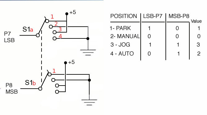
This is basically a two-line binary counter that returns a value of 0 thru 3 for the software to select the proper operating mode. After Greg designed this interface, he realized later that it could have been accomplished with only ONE Stamp pin by using analog resistive ladder sensing such as was done with the jog switches on P14. But what the heck... it works, and we didn't have a need for another unused pin.
The switch is a 2-pole, 4-position rotary switch. It can be ceramic or phenolic insulation. You can also use a rotary switch with more poles and positions, just leave the excess terminals unconnected.
AZIMUTH & ELEVATION POTS
P9
P10
These are the MANUAL adjustment pots that allow you to preset a "Go to" value on the meters and have the rotors track to these values. These controls utilize the Stamp's ability to read a resistance value with the RCTIME command.
HIGH AZPOT ; discharge the capacitor
PAUSE 1
RCTIME AZPOT,1,TEMP ;measure the charge time
AZDISPL=TEMP*AZSCALE/256 ;normalize reading
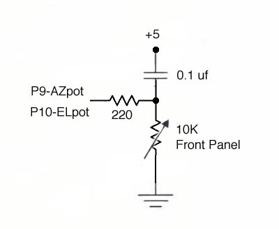
ERRATA: Greg and I noted 'foldover' at the high end of the pot travel. As a result, the capacitor value shown here was reduced for better discharge characteristics. I'm looking at a 0.05uf value now.
AZIMUTH & ELEVATION METERS
P11
P12
The controller program uses several internal representations of position. One is "Index", which is the number of contact closures the rotor has counted through from it's Zero position. The AZ rotor has a 5 degree rotation between closures (total of 72 per 360 degrees of travel), and the EL rotor also has a 5 degree resolution (36 for its 180 degrees of travel). A second representation is for the output to the meters. Here, the 360 degrees of a circle are compressed to 256, so that the PWM command can be used to drive the meters. In calculations, the ratio for 256/360 is reduced to 32/45 to fit the Stamp's 16-bit math. A simple analog buffer circuit is used to hold the PWM output, and to drive the meter. The 10K pot is used to set the full-scale meter indication. This circuit is repeated for the azimuth and elevation displays.
TEMP=AZDISPL*32*AZCOUNT/45 ;convert index to meter representation
PWM AZMETER,TEMP,50 ;send analog value to meter for display
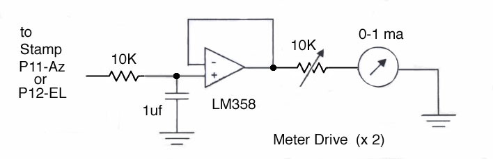
ERRATA: My meter readouts do not track the software properly and 'get ahead' of actual position. In addition I seem to have some 'crosstalk' between the AZ & EL readouts at times. I suspect there is some oscillation occurring in the dual-amp chip and I need to add some bypass caps on the IC leads. Need to get some bench test time with an oscilloscope probe in this circuit to see what is going on. Likely just bad construction as I 'crammed' this circuit into a small space on the Stamp carrier board. ...stay tuned for the fix.
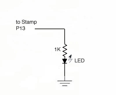
P13
SERIAL DATA ACTIVITY INDICATOR
This is simply a +5 volt drive to an LED to indicate data activity incoming on the PO serial data line. I wired this to a Yellow LED at the MODE selector switch "Auto" position. Note the current limiting resistor on this LED is 1K, limiting the current to 5ma so as not to load down the Stamp too much. Remember we are limited to 20ma total Stamp current loading.
JOG SWITCHES AZ & EL
P14
Here an analog technique is used to select four functions with only one bit line to the Stamp. Two SPDT-center-off switches are used to select one of four different resistors, with each direction command being represented by a different resistor. The Stamp's RCTIME function would be used again to read which switch had been activated.
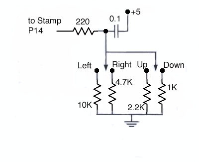
HIGH SWITCHES ;discharge capacitor
PAUSE 1
RCTIME SWITCHES,1,TEMP ;read switch setting
IF TEMP=0 THEN LOOP ;zero indicates no switches are active
IF TEMP>400 THEN SWLEFT ; each switch
IF TEMP>200 THEN SWRIGHT ; gives a different
IF TEMP>75 THEN SWUP ; value when pushed
GOTO SWDOWN ; actual value is between numbers tested
The switches are polled while the motor moves, so that you can stop at any time (at the next index mark) by letting go of the switch. Note that the circuit and software do not account for more than one switch being depressed at the same time. Just remember not to do that.
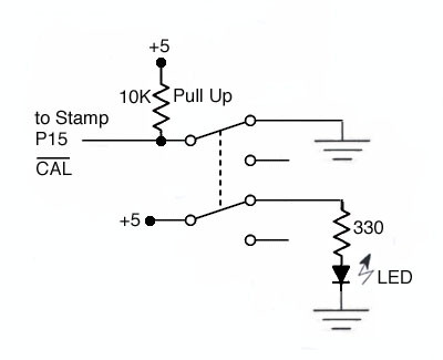
P15
CALIBRATE
This is a simple switch that grounds the P15 line for CALIBRATE mode. Do I really need to draw a diagram here? Well... OK. Perhaps I should explain the concept of a 'pull-up' resistor. This input line is seeking a low (ground) signal to become active. You don't want to leave this line disconnected and floating when not being used, as this is an indeterminate logic condition. It could 'sense' as anything! So we add the large value pull-up resistor to keep it up at a logic Hi (+5v) when the switch is open. Actually, I could have used the indicator LED in that position to perform that function also. But I had a double pole, double throw switch, and I chose to isolate the LED indicator... and teach you about pull-up resistors. So there...!
There are two scaling factors that are used in the operation of the controller, namely the conversion factors for the two manual position pots. The controller also must be synchronized once with the physical position of the rotors, since there is no way to "read" where a rotor is in absolute terms. A calibration routine is entered on power-up if the calibration mode pin (P15) is at a logic 0 state, which is smiply the result of grounding that pin on the stamp with a switch. Before beginning the calibration procedure, both of the manual position pots are turned to their maximum position. Then the calibration switch is set, and the controller is powered-up. The values of both pots is read and stored in the internal memory of the Stamp, where it is retained even when the controller is powered off. The internal memory is also used to save the AZ and EL rotor position at the end of each movement, so that the controller always knows where the rotors are. Both of the rotors are then rotated back toward the 0-degree stop. At each point in the process, the operator moves the main MODE switch to the next step when that step has completed. The rotation to 0-degrees is observed when the "Index" (yellow) LED stops flashing.
THE PBASIC SOFTWARE
You can download a copy of Greg's original KO6TH software here.
This is written in PBASIC (Parallax Basic) .BS2 for the Basic Stamp-2 microcontroller.
PBasic editing tools and software loading tools are available from the parallax website .
As of this writing I have now modified and loaded the software into my machine. It was my intent to modify the index-counting routines for my 5-degree/pulse rotor. This was easily deciphered from the original software where Greg indicated that his AZ rotor had 6-degree pulses, and the EL rotor had 10-degree pulses. The RED lines lines here indicate what I did.
Here is a text listing of the PBASIC program that Greg wrote, so you can learn for yourself how it all works.
5-Degree Rotor modifications noted in RED.
'
' Antenna Rotor control program
'
' (c) 2002 by Greg D. KO6TH
'
' version 1.0 2/27/00
' version 1.1 1/12/01 fix repeated write to flash for manual
' version 1.2 8/21/01 added incremental offset to automatic mode
' and serial reporting of position
'
' Stamp I/O bits
'
serial con 0 ' serial port to fodtrack
left con 1 ' drive to relay to decrease azimuth
leftp var out1 ' same pin for sampling state
right con 2 ' drive to relay to increase azimuth
rightp var out2 ' same pin for sampling state
azindex var in3 ' to index switch in az rotor (active low)
up con 4 ' drive to relay to increase elevation
upp var out4 ' same pin for sampling state
down con 5 ' drive to relay to decrease elevation
downp var out5 ' same pin for sampling state
elindex var in6 ' to index switch in el rotor (active low)
mode0 var in7 ' mode lsb
mode1 var in8 ' mode msb
azpot con 9 ' to RC/pot for manual azimuth control
elpot con 10 ' to RC/pot for manual elevaton control
azmeter con 11 ' PWM analog output 0-5v to az meter
elmeter con 12 ' PWM analog output 0-5v to el meter
serdata con 13 ' drive to serdata LED
switchs con 14 ' manual mode switches input
calib var in15 ' calibrate mode input (low = cal, high = normal)
'
'
' constants
'
knobdly con 10 ' # of 100ms loops for knob action delay
offmode con 1 ' offline mode
manmode con 0 ' manual mode
swtmode con 3 ' manual mode with switches
automod con 2 ' automatic (Fodtrack) mode
potjitter con 1 ' amount of variation in pot sense to be ignored
azcount con 6 ' # degrees per index for az (delete)
azcount con 5 ' modified for 5-degree rotor
elcount con 10 ' # degrees per index for el (delete)
elcount con 5 ' modified for 5-degree rotor
maxaz con 60 ' full rotation az counter (delete)
maxaz con 72 ' modified for 5-degree rotor
maxel con 36/2 ' full rotation el counter, limit to 1/2 rotation (delete)
maxel con 72/2 ' modified for 5-degree rotor
azindxt con 200 ' length of index pulse for az with margin
elindxt con 300 ' length of index pulse for el with margin (delete)
elindxt con 200 ' trim for 5-degree rotor
motorstop con 500 ' # ms to pause for motor to stop
maxoffset con 15 ' max # of offset index for nibble variable
baud con 16468 ' baud rate constant for serial-in - 9600,8,n
' EEPROM storage map
azsave data (1) ' az position in index form
elsave data (1) ' el position in index form
azcal data (2) ' max value of az pot RCTIME command
elcal data (2) ' max value of el pot RCTIME command
'
' variables
'
temp var word ' general register variable
azinput var word ' az read from serial port
elinput var word ' el read from serial port
azscale var word ' az calibration
elscale var word ' el calibration
temp2 var word ' another temp variable
modetimer var byte ' mode switch debounce timer
timer var byte ' pot adjustment timer
oldaz var byte ' previous az pot value
oldel var byte ' previous el pot value
azdispl var byte ' az meter value to be displayed
eldispl var byte ' el meter value to be displayed
azposn var byte ' current az index counter (0-59)
elposn var byte ' current el index counter (0-35)
dest var byte ' destination index for az/el move
mode var nib ' operating mode (0-3)
azoffset var nib ' az offset for automatic mode
eloffset var nib ' el offset for automatic mode
'
'
' initialization
low serdata ' turn off serial data ok LED
low left ' turn off all motor relays
low right
low up
low down
high azmeter
high elmeter
high serdata
pause 1000
mode = 15 ' start with illegal mode
modetimer = 0
timer = 0
read azsave,azposn ' fetch currenty position index
read elsave,elposn
azdispl = azposn ' set meters to current position
eldispl = elposn*2
read azcal,azscale.lowbyte ' fetch pot calibration
read azcal+1,azscale.highbyte
read elcal,elscale.lowbyte
read elcal+1,elscale.highbyte
oldaz = azposn ' assume pots are at current position
oldel = elposn
if calib = 0 then calibrate ' look at calibration input on power-up
' begin main loop here
loop:
' update meters. convert from index to meter form and send to meter
temp = azdispl*32*azcount/45
pwm azmeter,temp,50 ' 50 ms of pwm to set meter
temp = eldispl*32*elcount/45
pwm elmeter,temp,50
' check current mode based on panel switch
temp = mode1+mode1+mode0
if temp <> mode then newmode
if modetimer <> 0 then timemode
low serdata
branch mode,[manual,offline,auto,switchmode]
newmode: ' mode switch has changed
mode = temp
modetimer = knobdly
high serdata ' turn on LED
azoffset = maxoffset/2 ' clear offsets to midpoint
eloffset = maxoffset/2 ' clear offsets
goto loop
timemode: ' mode stable, decr timer and check again
modetimer = modetimer-1
if modetimer <> 0 then loop
low serdata
goto loop
' begin operating modes code
'
' manual positioning via pots. calculations made in meter (0-255) mode
' and then converted to indexes
'
offline: ' both offline and
manual: ' manual modes begin here
high azpot ' read az pot
pause 1
rctime azpot,1,temp ' 16 bit value
temp = temp*azscale/256
if abs(temp-oldaz) > potjitter then updateaz
high elpot ' read el pot
pause 1
rctime elpot,1,temp
temp = temp*elscale/256
if abs(temp-oldel) > potjitter then updateel
if timer = 0 then loop ' if no change and no timer, return to loop
timer = timer-1
if timer <> 0 then loop ' if change and timer still going, keep looking
' position change request complete, move antennas
if mode = offmode then loop ' don't move antennas if offline
azdispl = azposn ' restore meters to live position
eldispl = elposn*2
dest = oldaz*45/(32*azcount) ' set index position desired
gosub moveaz ' move antenna
write azsave,azposn ' store new position back in flash
dest = oldel*45/(32*elcount)/2 ' elevation scale 0-180
gosub moveel ' ... and oldel
write elsave,elposn ' store new position back in flash
debug "AZ = ",dec azposn*azcount,", EL = ",dec elposn*elcount,cr
goto loop
updateaz: ' display new position and start timer
oldaz = temp ' convert to index 0..59
azdispl = oldaz*45/(32*azcount)
timer = knobdly
goto loop
updateel:
oldel = temp ' convert to index 0..36
eldispl = oldel*45/(32*elcount)
timer = knobdly
goto loop
'
' Automatic mode
'
' Yaesu format: serial data = Waaa eee<cr>
'
auto: ' automatic (fodtrack/yaesu) mode
azdispl = azposn ' update meters & logical pot setting
eldispl = elposn*2
oldaz = azdispl*azcount*32/45
oldel = eldispl*elcount*64/45
serin serial,baud,2000,noserial,[wait("W"),DEC azinput,DEC elinput]
high serdata ' turn on LED showing data received
temp = (azinput/azcount)+azoffset-(maxoffset/2) ' convert to index
if temp >= 0 then autoaz1
temp = temp+maxaz
autoaz1:
if temp < maxaz then autotestaz
temp = temp-maxaz
autotestaz:
if temp <> azposn then autoaz
autodoel:
temp = (elinput/elcount)+eloffset-(maxoffset/2)
if temp >= 0 then autoel1
temp = 0
autoel1:
if temp < maxel then autotestel
temp = temp-maxel
autotestel:
if temp <> elposn then autoel
' check increment switches
autoincr:
high switchs ' read switch positions
pause 1
rctime switchs,1,temp
if temp = 0 then loop ' if nothing active, done.
high serdata ' turn on led
incroff:
high switchs ' read switch positions again
pause 1
rctime switchs,1,temp2
if temp2 <> 0 then incroff ' loop until switch is returned
low serdata ' acknowledge switch has been read
if temp > 400 then incrleft
if temp > 200 then incrright
if temp > 75 then incrup
goto incrdown
incrleft:
if azoffset = 0 then loop
azoffset = azoffset-1
goto loop
incrright:
if azoffset = maxoffset then loop
azoffset = azoffset+1
goto loop
incrup:
if eloffset = maxoffset then loop
eloffset = eloffset+1
goto loop
incrdown:
if eloffset = 0 then loop
eloffset = eloffset-1
goto loop
autoaz:
dest = temp
gosub moveaz
write azsave,azposn
debug "AZ = ",dec azposn*azcount,", EL = ",dec elposn*elcount,cr
oldaz = azposn*32*azcount/45
goto autodoel
autoel:
dest = temp
gosub moveel
write elsave,elposn
debug "AZ = ",dec azposn*azcount,", EL = ",dec elposn*elcount,cr
oldel = elposn*64*elcount/45
goto autoincr
noserial:
high serdata
pause 5 ' wait just long enough to see LED blink
low serdata
goto autoincr ' check offset switches then loop
'
' Manual mode with switches
'
switchmode:
high switchs ' read switch positions
pause 1
rctime switchs,1,temp
if temp = 0 then loop
switchloop:
high switchs ' read switch positions
pause 1
rctime switchs,1,temp
if temp = 0 then swnone
temp2 = azposn*azcount*32/45
pwm azmeter,temp2,50 ' 50 ms of pwm to set meter
temp2 = elposn*elcount*64/45
pwm elmeter,temp2,50 ' 50 ms of pwm to set meter
if temp > 400 then swleft
if temp > 200 then swright
if temp > 75 then swup
goto swdown
swleft:
if azposn = 0 then swnone
if rightp+upp+downp <> 0 then swnone
high left
gosub azindxwait
azposn = azposn-1
goto switchloop
swright:
if azposn >= maxaz then swnone
if leftp+upp+downp <> 0 then swnone
high right
gosub azindxwait
azposn = azposn+1
goto switchloop
swdown:
if elposn = 0 then swnone
if upp+leftp+rightp <> 0 then swnone
high down
gosub elindxwait
elposn = elposn-1
goto switchloop
swup:
if elposn >= maxel then swnone
if downp+leftp+rightp <> 0 then swnone
high up
gosub elindxwait
elposn = elposn+1
goto switchloop
swnone:
low down
low up
low left
low right
pause motorstop
write azsave,azposn
write elsave,elposn
debug "AZ = ",dec azposn*azcount,", EL = ",dec elposn*elcount,cr
azdispl = azposn
eldispl = elposn*2
goto loop
' Calibration Routine
'
' Process: Ground calib pin before power-up to enter calibration process
'
' turn both az and el pots to max clockwise positon
' set to 1st mode position, then turn on. serdata light comes on, then off
' turn mode to next position. AZ rotor moves to 0 degrees
' turn mode to next position. El rotor moves to 0 degrees
' turn last position to end calibration phase
'
calibrate:
high serdata ' turn on acknowledgement
high azpot ' read az pot
pause 1
rctime azpot,1,temp ' 16 bit value
temp = 65535/temp
write azcal,temp.lowbyte ' save
write azcal+1,temp.highbyte
high elpot ' read el pot
pause 1
rctime elpot,1,temp
temp = 65535/temp
write elcal,temp.lowbyte
write elcal+1,temp.highbyte
pause 1000
low serdata
high azmeter ' set meters to full scale
high elmeter
cal1: if mode1+mode1+mode0 = offmode then cal1
low azmeter ' return meters to zero
low elmeter
high left ' turn on az motor toward zero
cal2: if mode1+mode1+mode0 = manmode then cal2 ' wait till there
low left
pause motorstop
write azsave,0
high down ' head el motor toward 0
cal3: if mode1+mode1+mode0 = automod then cal3
low down
pause motorstop
write elsave,0
cal4:
toggle serdata
pause 1000
goto cal4
''''''''''''''''''''''''''''''
' move az rotor
' input: dest is index position desired
' azposn is real position in index form
'
' output: meter & azdispl updated to new position
' azposn updated to new real position
moveaz:
temp = azposn*azcount*32/45
pwm azmeter,temp,50
if dest = azposn then rtn
if dest > azposn then moveright ' if need to increase az...
' move left (decrease az)
high left ' start motor for CCW rotation (decr az)
moveazl:
gosub azindxwait ' wait for next index pulse
azposn = azposn-1 ' update position
temp = azposn*azcount*32/45
pwm azmeter,temp,50 ' 50 ms of pwm to set meter
if dest < azposn then moveazl ' if still need to move...
low left ' turn off motor
azdone:
pause motorstop ' wait for motor to stop
azdispl = azposn ' set display
rtn:
return
' move right (increase az)
moveright:
high right ' start motor for CW rotation (incr az)
moveazr:
gosub azindxwait ' wait for next index pulse
azposn = azposn+1 ' update position
temp = azposn*azcount*32/45
pwm azmeter,temp,50 ' 50 ms of pwm to set meter
if dest > azposn then moveazr ' if still need to move...
low right ' turn off motor
goto azdone
''''''''''''''''''''''''''''''
' move el rotor
' input: dest is meter position desired
' elposn is real position in index form
'
moveel:
temp = elposn*elcount*64/45
pwm elmeter,temp,50
if dest = elposn then rtnel
if dest > elposn then moveup ' if need to increase el...
' move down (decrease el)
high down ' start motor for CCW rotation (decr el)
moveeld:
gosub elindxwait ' wait for next index pulse
elposn = elposn-1 ' update position
temp = elposn*elcount*64/45
pwm elmeter,temp,50 ' 50 ms of pwm to set meter
if dest < elposn then moveeld ' if still need to move...
low down ' turn off motor
eldone:
pause motorstop ' wait for motor to stop
eldispl = elposn*2
rtnel:
return
' move up (increase el)
'
moveup:
high up ' start motor for CW rotation (incr el)
moveelu:
gosub elindxwait ' wait for next index pulse
elposn = elposn+1 ' update position
temp = elposn*elcount*64/45
pwm elmeter,temp,50 ' 50 ms of pwm to set meter
if dest > elposn then moveelu ' if still need to move...
low up ' turn off motor
goto eldone
''''''''''''''''''''''''''''''
' wait one index pulse on az
'
azindxwait:
if azindex= 0 then azindxwait ' if already at index, wait first
wait1:
if azindex=1 then wait1 ' wait for index to start
pause azindxt ' delay for index to end
return
'
''''''''''''''''''''''''''''''
' wait one index pulse on el
'
elindxwait:
if elindex = 0 then elindxwait ' if already at index, wait first
wait1e:
if elindex=1 then wait1e ' wait for index to start
pause elindxt ' delay for index to end
return