Small Antennas for HF
Living in urban Honolulu one finds that space is at a premium. I was a condominium apartment dweller for decades, and antennas were always a challenge, usually limited to VHF or small balcony compromise antennas, surrounded by concrete sheilding. These didn't make for the best of signals. And the condominium rules usually prohibited anything excessive or even visible!
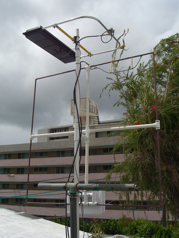
Recently I moved my QTH to another nearby apartment that is a privately owned 4-plex with no condo-rules (Joy!). I have a good relationship with the landlord, and he doesn't mind my erecting some antennas adjacent to my apartment. The place is on a hillside, and I have a narrow 'backyard' on a ledge just wide enough for some laundry machines and a clothesline, with a reasonable sky exposure that includes a nice wide wedge to the east for some local satellite work. The iron clothesline posts make good supports to strap some PVC pipe supports to, so I came up with this odd looking arrangement...
I told the landlord I would keep the brushy tree trimmed for him, and he appreciates that. I keep the branches out of my antennas that way.
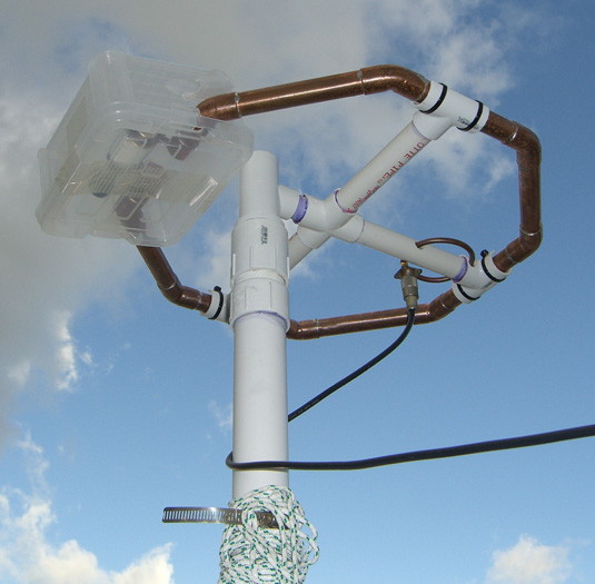
On the top, mounted horizontally, is an old AEA IsoLoop that is good for 20-15-10 meters. The black plastic box contains a wide-spaced air variable capacitor that is remotely tuned from a small control box inside the shack. I don't believe this version of the IsoLoop is made anymore, but there are more modern versions available by several different manufacturers. Note that the feedpoint is a small, isolated loop that inductively couples to the larger ring that is resonated by the capacitor in the box.
40 METERS
Now I wanted something that would also work on 40 meters as there are several statewide interisland nets on 40M in Hawaii, and this could prove valuable in times of emergency. After a lot of research on magnetic loops, I settled on this one by Peter Parker, VK3YE. Another good article on this, with comments is published here by IW5EDI. So what I have here is a 5-foot square of 1/2" copper pipe supported by a PVC frame with a center X mount for vertical support. The diagram says the loop is tuned by a 400pf variable capacitor.
Note the feedpoint is at the top of the antenna. This was determined experimentally, and seems to be kind of a hybrid between a parallel gamma match and an inductive loop. I found the best match point by sliding the center conductor feed along the loop side, and then found I got even better coupling by bowing the feedline out into a larger loop for better magnetic coupling. The result is the strangely shaped feedpoint that bows inward and then connects to the loop.
My early tries using an air variable capacitor were frustrating. With only 180 degrees of rotation it was hard to tune, and the plate spacing was inadequate to handle even a modest amount of power without arcing over. Finally I went on eBay and found a Russian surplus vacuum variable from the Ukraine, rated at 10-500pf at 10kV for about $129. Not a bad price,about 10% compared to new ones.
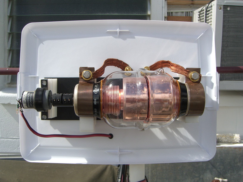
I cut teflon blocks to mount it, fashioned copper strap clamps for the end caps, and used copper braid to connect it to the ends of the loop behind. An insulated bushing and 1-rpm gearmotor drive the tuning shaft. The whole assembly is mounted on a metal plate for rigid support, and that in turn is mounted to a reinforced PVC framework on the back. The assembly is enclosed in a poly 'shoe box' to weatherproof it.
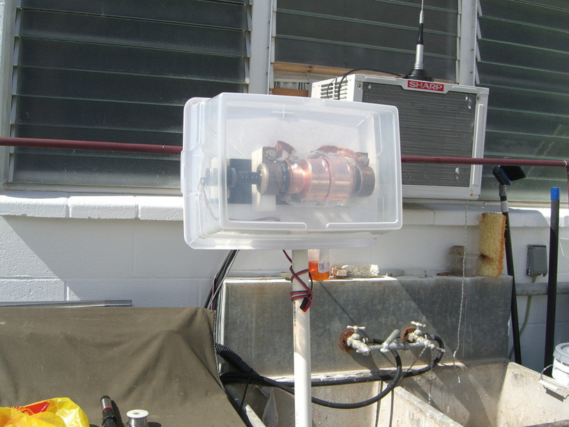
Due to the weight, and need for accessibility, this box became the bottom of the loop as the loop was screwed on to the centerpoint mounting. The vacuum variable has about 35 turns across it's range and tunes easily and slowly with the 1-rpm motor. I find that 40 meters seems to be about 3 or 4 turns in from minimum capacitance. This loop is supposed to be able to tune 80 meters also, at the far end of maximum capacitance. In truth, I have not tried it yet, as it would be a real tuning chore to hold my spring-toggle switch for close to half an hour for 1-rpm to go 30-some turns on the capacitor. I have no turns counter, so I would have to track position by using a good stopwatch... all while listening to the receiver for a good noise peak as resonance is reached on the antenna!
That might make me even more loopy than I already am!
SO HOW DOES IT WORK?
Very well, thank you! The loop is oriented vertically and East-West. This takes advantage of NVIS, or Near-Vertical Incident Skywave propagation in the ionosphere, maximized in the E-W directions along the loop's edge plane. For the short-range communications of a couple hundred miles along the island chain, this is the form of propagation that works best. After checking in to the afternoon net on 7.088 MHz (Note: we're in the tropical pacific. That is not a frequency that mainland US hams can use!) I find I have an excellent signal to both ends of the State. Using only 50 watts, I was getting a signal report of +10 over S9 from downtown Hilo, on the far side of the volcano on the Big Island of Hawaii, about 250 miles distant.
SIX METERS - 50 MHz
The solar cycle is on the upswing now in 2012, so it's time to get something up on six meters.
Last cycle I was using a small dipole and later a loop made out of 4-inch wide copper strap with a 3-30pf vacuum variable cap for tuning. I managed to contact Pitcairn Island and Kingman Reef on six with that loop, as well as nightly grey-line contacts all along the Australian coastline. The copper strap has long been hacked, but I still have the 3-30pf vacuum variable to use. Here is a great website for calculating the design of a magnetic loop antenna:
http://www.66pacific.com/calculators/small_tx_loop_calc.aspx
So off to the plumbing shop for some 3/4" copper pipe and 45-degree elbows.
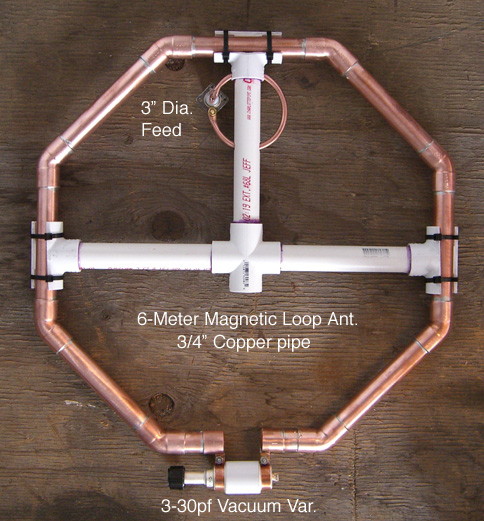
I based the design on a conductor length of 4.7 feet with the above calculator, which is about maximum length acceptable, and then foreshortened the straight length cuts to an even 6 inches (0.5 ft instead of the calculated 0.588 ft.) just for convenience of measurement. The elbow angles make up some fractional length there, as well as the diameter of the pipe. It should tune 50.1 MHz with about 12pf on the capacitor, with an efficiency above 90% on the antenna, and a bandwidth of over 240 kHz.
The feedpoint loop is supposed to be 1/5 to 1/6 the diameter of the big resonant loop, so I made a nominal 3-inch diameter ring of 1/8" 'icemaker" soft copper water line. About 9-1/4" length bent into a circle and soldered to the coax connector, and supported by the PVC arm should work nicely. I'm going for some serious power handling capability here, in case I try to hook up the FET 'Killer-Watt' Amp (tm) to it!
The whole assembly is supported horizontally by 3/4" PVC pipe, X-crossover and sliced T-connectors to support the ring and feedpoint. Just a smaller version of the supports I used on the 40-meter loop above.
I suppose I will find another small polyethylene box to provide a raincover for the vacuum cap. With any luck, the thing will not light up with a blue ion-glow under power!
I'm kind of lucky to have a broadcast TV maintenance shop for my use. I preset the vacuum variable cap at 12pf using a Sencore Z-meter before assembly. Later I swept the antenna on the H-P network analyzer and watched it draw a graph of the tuning response of the antenna. Set a marker for 50.125 mHz and fine tuned the cap for the resonant dip there. It was very, very close already! Nice to see theory actually pan out under test.
I have a few extra 3-30pf vacuum variables available if anyone is interested in building one of these.
Contact me at
kh6hak (at) arrl (dot) net